Monday, 11 December 2017
Saturday, 9 December 2017
ship security officer
With reference to ISPS code what are
the responsibilities of “Ship Security Officer”?
- Implementing and maintaining the ship security plan (SSP)
- Conducting security inspections at regular intervals of time to ensure that proper security steps are taken
- Making changes to the ship security plan if need arise
- Propose modifications to the ship security plan by taking various aspects of the ship into consideration
- Help in ship security assessment (SSA)
- Ensure that the ship’s crew is properly trained to maintain a high ship security level
- Enhance security awareness and vigilance on board ship
- Guide ship’s crew by teaching ways to enhance ship’s security
- Report all security incidents to the company and the ship’s master
- Taking view and suggestions of the company security officer and the port facility security officer into consideration while making amendments to the ship security plan
- Help company security officer (CSO) in his duties
- Take into account various security measures related to handling of cargo, engine room operations, ship’s store etc.
- Coordinate with ship board personnel and port authorities to carry out all ship operations with utmost security
- Ensure that the ship security equipment is properly operated, tested, calibrated, and maintained
Friday, 3 November 2017
Thursday, 2 November 2017
crankcase inspection
List the items to
be checked during crankcase inspection of a large Marine Diesel Engine
Safety Precautions carried Out before Crankcase Inspection:
·
Inform
bridge and chief engineer.
·
If in
port take immobilization certificate.
·
Get
propeller clearance from duty officer.
·
Shut off
starting air valve.
·
Put man
at work tag
·
Stop
lube oil pump.
·
Indicator
cocks to be opened.
·
Turning
gears to be engaged.
·
Ventilate
crankcase door properly.
checks
- Firstly check oil condition for any smell, discoloration or degradation.
- Check the piston rod surface for scoring marks and roughness.
- Check piston palm bolts and locking device for slackness and fretting.
- CHECK THE guide shoe and area around it.
- Check cross head bearing general condition.
- Evaluate top and bottom end of connecting rod bolt, nut and locking device for slackness, signs of fretting, etc.
- Check for slip of web and journal by checking the reference mark.
- Check crankcase relief door spring tension, wire mesh and & sealing ring.
- Check the axial movement of bottom end bearing.
- Check and clear O.M.D sampling pipe.
Wednesday, 1 November 2017
oil fire in the bilge
If there be an oil fire in the bilges, what
type of fire extinguisher would you use and why?
answer:
- First check the condition of fire;
it is small oil fire in the bilge well.
- Then raise the fire alarm signal.
- Remove the combustible material near
vicinity.
- It is a small fire, extinguish by
foam portable extinguisher.
- Release the foam direct to the fire
by deflecting it from another surface.
- Foam is lower specific gravity than
oil or water that it will flows across the surface of oil and cover.
- The fire will stop by blanking with
foam.
man-hole cover
What precautions would you take before
opening a man-hole cover of a fuel tank?
answer:
- Gas free certificate
- Tank entry permit
- Risk assessment.
- Test tank atmosphere for toxic gases
and oxygen.
- Breathing apparatus, resuscitation
equipment to be kept ready at entrance.
- Life line to be put on.
- A spark proof hand torch light to be
brought in
- Competent person to be kept on watch
- Smoking and naked light not allowed
in vicinity.
Tuesday, 31 October 2017
CRUDE OIL WASHING(COW)
WHAT
IS COW?
Crude oil washing (COW) is a system
whereby oil tanks on a tanker are cleaned out between voyages not with water,
but with crude oil - the cargo itself
The solvent action of the crude oil makes the cleaning process far more effective than when water is used.
The system helps prevent pollution of the seas from operational measures.
MARPOL Annex I Regulation 13 (6) requires every new crude oil tanker of 20,000 tons dead weight and above to be fitted with a cargo tank cleaning system using crude oil washing.
WHY
COW?
•Previously, oil tanks on crude oil tanker
were cleaned by water but this method of cleaning increased marine pollution and required bigger slop tanks to store left over residue
and oil water mixture.
•In order to prevent this problem, a better non pollutant way was introduced where in oil carg of the tank itself was used to clean the cargo tanks.
•When oil cargo is sprayed with pressure on tank walls and surfaces, the sediments sticking to the tank dissolves and converts into useful cargo which can be pumped out to the shore tanks.
•This system virtually eliminates the requirement of slop tanks on ships and almost all cargo can be transferred to the shore.
•Maintaining a pressure of at least 10 bar assists this process.
Before
starting the operation
•confirm all pre arrival checks are
performed.
•The complete COW operation to be
discussed with ship and shore staff.
•Signal and Emergency signs to be
discussed to stop the operation between
shore and ship staff.
•Inert Gas plant to be working and oxygen
content must be less than 5 %.
•Fixed Oxygen analyser to be checked and
calibrated for proper functioning.
•Portable oxygen analyser should be made
available and checked for proper
functioning.
When
the operation is under process
•The inert gas values to be frequently
checked- Tank pressure and O2 value.
•A responsible person to be always present
on deck.
•All deck lines and valves must be
frequently checked for any leakages.
•Trim should be sufficient to assist the
bottom washing of tanks.
The level of holding tanks to be
continuously monitored to avoid overflow.
When
the Operation is finished
•Drain tank wash line off crude oil
•Shut all the valves in the line used for
the operation
•Stop and drain all the machines involved
in the operation
•Drain all the cargo pumps after the
operation is finished
Suspending
Crude Oil Washing
Suspend
COW operations immediately if:
•The oxygen content of Inert Gas being
supplied exceeds 8% by Volume.
•Any indication of cargo oil leakage or
malfunction in the COW system.
•COW operation is not carried out in
accordance with the COW operation plan, or if communication between the CCR and
main deck is lost.
•If the required necessary safety
precautions as described and covered above cannot be followed.
•If terminal instruct to do so
Monday, 23 October 2017
REQUIREMENT TO COOL ENGINE PARTS
Question: Why it is necessary to cool
(1) cylinder head
(2) cylinder liner
(3) piston of diesel engine
Answer:
Temperature inside the cylinder may rise to 2000 degree c during combustion and drops to 600 degree c at the end of expansion. so a temperature gradient is created.
with temperature in this range, these components would get heated up quickely to a point where its strength would be insufficient to withstand cylinder pressure.
No oil film would be able to exist on the cylinder wall
Lubrication of the cylinder and piston ring would break down.
Medium of cooling:
Cylinder liner- Fresh water
Piston- fresh water( older engines), oil( new engines)
Saturday, 14 October 2017
PISTON RINGS
PISTON RINGS
Types:
1. Compression rings
2. scrapper rings
Compression rings
Higher speed engine uses less rings then low-speed engines because of the fact that higher piston speeds lessen the possibility of a blow-by.
Q. HOW SEALING EFFECT IS PROVIDED BY COMPRESSION RING?
A. due to the pressure of the gases entering the so-called back clearance b/w the piston and ring and partly due to ring tension.
Maximum gas pressure comes onto the first and second rings next to the combustion chamber.
Pressure decreases for the lower rings due to the throttling effect of the labyrinth formed by the back clearance.
TYPE OF LUBRICATION FOR COMPRESSION RING
Hydrodynamic Lubrication
SHAPE OF JOINT
Types:
1. Compression rings
2. scrapper rings
Compression rings
- Fitted into grooves provided in the piston crown.
- serves to prevent blow-bys.
Higher speed engine uses less rings then low-speed engines because of the fact that higher piston speeds lessen the possibility of a blow-by.
Q. HOW SEALING EFFECT IS PROVIDED BY COMPRESSION RING?
A. due to the pressure of the gases entering the so-called back clearance b/w the piston and ring and partly due to ring tension.
Maximum gas pressure comes onto the first and second rings next to the combustion chamber.
Pressure decreases for the lower rings due to the throttling effect of the labyrinth formed by the back clearance.
TYPE OF LUBRICATION FOR COMPRESSION RING
Hydrodynamic Lubrication
- To ensure ring tension and allow for the expansion of the rings as they become hot, joints are provided in the rings.
- Ring diameter in a free state is always larger then the bore.
SHAPE OF JOINT
- Straight
- Bevelled
- Stepped
- Low speed diesel engines employ bevelled and stepped joints
- High speed diesel engines employ straight joint.
- Experiment proves that the piston rings rotates in the operation.
- On the other hand it is desirable that on 2-stroke engines the piston ring retain their original position so that no joint would appear against the ports in the cylinder liner and become trapped and broken when the engine is running.
- Special retainers are integrally made with the piston ring serve to secure this in place.
Friday, 13 October 2017
Some important definition
Displacement
Dead-weight
Light-weight
Draught
Depth
Freeboard
Reserve buoyancy
keel
Hull
Bow
Stern
Amidship
Buoyancy
Bullwark
Free surface effect
Dead-weight
Light-weight
Draught
Depth
Freeboard
Reserve buoyancy
keel
Hull
Bow
Stern
Amidship
Buoyancy
Bullwark
Free surface effect
PROTECTION AND INDEMNITY CLUB(P & I CLUB)
Let's know about P & I CLUB
- Formed by shipowners in order to secure cover which are not included in marine insurance policy.
- The maintenance of these cubs is secured by way of a levy upon the amount of tonnage owned by the members of the club, each making proportionate payment to the funds to the club.
The club is divided into two sections, namely, protection and indemnity and usually covers the following risks:
PROTECTION
- cases of loss of life or personal injury
- Repatriation of distressed seamen, and any expenses for hospital and medical attention
- Loss of life following collision.
- Loss or damage by collision to another vessel, including one-quarter of the value of the cargo on board -it being remembered that three-quarters of the cargo is covered under the marine policies.
- Loss or damage to cargo arising from improper navigation.
- Cargo's proportion of general average arising from improper navigation.
- Cost of rising wreck.
- Cost of department of trade inquiries.
- Legal cost of defending claims.
INDEMNITY
- Wrong, short, or mixed delivery of cargo.
- Ship's liability following collision, which is not covered by insurance.
- Cost of fines which may be caused by the barratry and wrongful acts of the master and/or crew.
- Cost of resisting cargo claims.
FUEL BOOSTER PUMP
- To induce continuous flow of fuel from service tank to the fuel injection pumps, booster pump is used which is incorporated in fuel line
- A booster pump must supply oil at pressure sufficient to overcome frictional resistance of filters, lines.
- For marine practice booster pumps are of reciprocating, vane and centrifugal type.
- Usually gear pump is used as a booster pump capable of creating suction lift of 1-1.5 m h2o.
Tuesday, 26 September 2017
FUEL SYSTEM
RELATED QUESTIONS:-
- WHAT ARE THE MAIN COMPONENTS OF FUEL SYSTEM?
- IN WHICH WAY FUEL IS SEPARATED FROM SEDIMENTS?
- WHAT IS THE FUNCTION OF FUEL BOOSTER PUMP? WHAT TYPE OF FUEL BOOSTER PUMP DO YOU HAVE? DISCUSS THEIR OPERATION.
- WHAT PURPOSE DOES THE FUEL-INJECTION PUMP SERVES?
- WHAT IS THE FUNCTION OF FUEL INJECTOR?
- DISCUSS THE OPERATION OF FUEL INJECTOR.
- WHAT IS THE PRINCIPAL MALFUNCTIONS OF THE FUEL EQUIPMENT?
- TEST AND OVERHAUL OF FUEL INJECTION VALVES.
- REASONS FOR FUEL VALVE SEIZURE.
- HOW FUEL INJECTOR IS BEING COOLED COMPARE BETWEEN OLDER ENGINE AND NEWER ENGINE.
- HOW TO CHANGE THE TIMING OF FUEL INJECTION?
- OPERATION OF VIT AND SUPER VIT?
- REQUIREMENTS OF CRANKCASE OIL AND CYLINDER LUBRICATION OIL.
- DIFFERENT TYPES OF TEST CARRIED OUT ON LUBE OIL?
- HOW TO UPKEEP THE QUALITY OF LUBE OIL ONBOARD SHIP?
- CATEGORIZE CRUDE OIL?
- DEFINE MICROBIAL DEGRADATION OF FUEL OIL.
- MICROBIAL DEGRADATION OF LUBE OIL , ITS CAUSE AND EFFECT AND THE METHOD OF INDICATION?
Thursday, 21 September 2017
VARIOUS TOOLS
 |
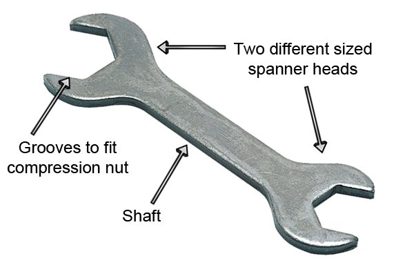
| OPEN ENDED SPANNER |
| RING SPANNER |
| ADJUSTABLE SPANNER |
 |
| RACHET SPANNER |
| NUT BOLT ASSEMBLY |
 |
| SCREW DRIVER |
| PLIERS |
 |
| NOSE PLIER |
 |
| HAMMER |
| BENCH VICE |
 |
| HACKSAW |
 |
| HATCHET |
 |
| SAW |
 |
| HAND DRILL |
 |
| CHISEL |
 |
| SCRAPPER |
| DRILL BIT |
| L SHAPE RIGHT ANGLE |
 |
| DRILLING MACHINE |
 |
| HAND DRILLING MACHINE |
 |
| HAND VICE |
 |
| TORQUE SPANNER |
 |
| ALLEN-KEY |
 |
| FILLER GAUGE |
| PIPE WRINCH |
 |
| VERNIER CALIPER |
 |
| DIAL GAUGE |
 |
| SCREW GAUGE |
| BRIDGE GAUGE |
| OIL CAN |
 |
| MEASURING TAPE |
 |
| WIRE CUTTER |
| AIR CONDITIONING COPPER PIPE CUTTER |
 |
| PULLER |
Tuesday, 19 September 2017
AIR BOLLTE
AIR BOTTLE USED ON-BOARD SHIP

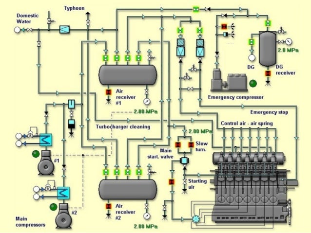
- IT IS A LARGE CONTAINER USED TO STORE COMPRESSED AIR.
- IS IS ALSO KNOWN AS AIR RECEIVER AS IT ACTS AS AN AIR RESERVOIR.
- PRESSURE OF COMPRESSED AIR IS AROUND 25-30 BAR.
PURPOSE
1. MAIN PURPOSE IS TO START MAIN ENGINE AND AUXILIARY ENGINE.
2. SUPPLIES CONTROL AIR TO MARINE ENGINES.
3. USED IN VARIOUS PNEUMATICALLY CONTROLLED DEVICES SUCH AS IF QUICK CLOSING VALVE IS PNEUMATICALLY OPERATED.
4. HYDROPHORE SYSTEM TO SUPPLY WATER AT A CERTAIN PRESSURE USES COMPRESSED AIR.
5. SPRING AIR FOR EXHAUST VALVE IS SUPPLIED THROUGH AIR BOTTLE.
6. FOR CLEANING PURPOSES WHICH REQUIRES COMPRESSED AIR SUCH AS FILTERS.
SOLAS REQUIREMENTS
- THE CAPACITY OF AIR BOTTLE SHOULD BE SUCH THAT IT IS CAPABLE ENOUGH TO PROVIDE 12 CONSECUTIVE STARTS FOR REVERSIBLE ENGINE AND 6 CONSECUTIVE STARTS FOR NON-REVERSIBLE ENGINES.
- SOLAS PRESCRIBES THAT THERE MUST BE AT LEAST TWO IDENTICAL MAIN AIR BOTTLE AND ONE EMERGENCY BOTTLE ON EVERY VESSEL.
SAFETY DEVICES FITTED ON AIR BOTTLE
1. RELIEF VALVE
2. DRAIN VALVE
3. FUSIBLE PLUG
4. ALARMkps3005@gmail.com
5. PRESSURE GAUGE
SOME OTHER MOUNTINGS ARE
1. MAIN VALVE FOR STARTING AIR TO MAIN ENGINE
2. VALVE FOR AIR START TO AUXILIARY ENGINE
3. INLET VALVE FOR MAIN AIR COMPRESSOR
4. MANHOLE DOOR FOR INSPECTION PURPOSE (ELLIPTICAL SHAPE)
PURPOSE OF ALARM
- AIR BOTTLE LOW PRESSURE ALARM IS FITTED ON THE RECEIVER.
- ACTIVATION OF THIS VALVE IMPLIES THAT THERE IS NOT ENOUGH AIR IN THE BOTTLE.
- SO MAIN ENGINE OR AUXILIARY ENGINE CAN NOT BE STARTED IN THIS CONDITION.
DURING EVERY WATCH
- MUST DRAIN THE AIR BOTTLE.
- KEEP DRAIN VALVE OPENED TILL ALL THE MOISTURE IS DRAINED.
- IF MOISTURE CARRYOVER TAKES PLACE ALONG WITH COMPRESSED AIR , IT WILL CORRODE AIR BOTTLE.
- IN ABSENCE OF DRAINING PROCEDURE OIL CARRYOVER WILL TAKE PLACE AND MAY RESULT IN FIRE.
MATERIAL
MADE UP OF CAST IRON.
INTERNAL SURFACE IS COATED WITH ANTI-CORROSIVE MATERIAL.

Monday, 18 September 2017
DIESEL CYCLE
DIESEL CYCLE (constant pressure cycle)

The cycle was first analysed by Rudolf Diesel
1-2:- isentropic compression
2-3:- heat addition at constant pressure
3:- heat supply is cut-off
3-4: isentropic expansion
4-1:- heat rejection at constant volume
Compression ratio=v1/v2
- It is an ideal cycle.
- It must be made clear that this does not represent what actually happens inside the cylinder of a working diesel engine.
- It was developed to be able to model engine behaviour and to analyze the effects of certain changes to the cycle without the complications of modelling an actual engine cycle.
Like an indicator diagram it is a graph of Pressure against Volume, but it makes certain assumptions:
(a) The mass of air within the cylinder remains the same: There are no inlet or exhaust valves.
(b) Fuel is not injected and burnt, but heat energy is added at constant pressure.
(c) At the end of the cycle the heat energy is rejected at constant volume.
(d) The compression and expansion of the air is adiabatic (no heat energy is added or lost) and follows the law (pv^y=c)
where c is a constant , for y air is 1.4.
NOTE:- Thermal efficiency of diesel engine is always less then otto engine for same compression ratio.(mathematically can be shown)
Sunday, 17 September 2017
CENTRAL COOLING SYSTEM
- TO PREVENT PROBLEMS ASSOCIATED WITH SALT WATER SYSTEM FRESH WATER IS USED FOR COOLING ALL THE COMPONENTS WHICH FORMS A CLOSED SYSTEM.
- · SALT WATER PASSES THROUGH ONLY ONE SET OF PUMPS, VALVES, AND FILTER AND A SHORT LENGTH OF PIPING.
- · THE SEA WATER TAKES WATER FROM THE SUCTIONS ON EITHER SIDE OF THE MACHINERY SPACE AND AFTER PASSING THROUGH THE COOLER IT IS DISCHARGED STRAIGHT OVERBOARD.
- THE FRESH WATER IN THE CLOSED SYSTEM IS TREATED WITH CHEMICALS TO PREVENT CORROSION OF THE PIPEWORK AND COOLERS. WITH CORRECT CHEMICAL TREATMENT, CORROSION IS ELIMINATED IN THE FRESH WATER SYSTEM, WITHOUT THE NEED FOR EXPENSIVE MATERIAL.
- IT CAN BE DIVIDED INTO THREE SECTIONS:-
1. SEA WATER CIRCUIT
2. HIGH TEMPERATURE CIRCUIT
3. LOW TEMPERATURE CIRCUIT
2. HIGH TEMPERATURE CIRCUIT
3. LOW TEMPERATURE CIRCUIT
COMBINATION OF THESE IS KNOWN AS CENTRALISED COOLING SYSTEM.
- THE OUTLET OF JACKET COOLING WATER IS USED FOR THE EVAPORATION OF SEA WATER (FRESH WATER GENERATOR).
- HIGH TEMPERATURE SYSTEM(HT) IS USED FOR
- MAIN ENGINE LINER COOLING
-CYLINDER HEAD COOLING
-EXHAUST VALVE COOLING
- · LOW TEMPERATURE(LT) USED FOR:-
§ FUEL VALVE COOLERS
§ AIR CONDITIONING CONDENSER
§ SHAFT BEARINGS
§ HYDRAULIC OIL COOLERS
§ MAIN AIR COMPRESSOR
. MAIN ENGINE AIR COOLER
. LUBE OIL COOLER
Subscribe to:
Comments (Atom)
