Showing posts with label marine auxiliary. Show all posts

Tuesday, 17 April 2018

marine auxiliary objective questions

              MARINE AUXILIARY 


Q1- During shutting down the purifier you find that purifier always vibrates heavily for some time and then becomes normal until it finally comes to a stop. What should be done to avoid this situation?
A. The purifier bowl should be cleaned before next startup
B. The brake should be applied so that the critical speed doesnot last long
C. Complete overhaul of the purifier should be carried out and the bearings need to be renewed
D. The bowl should be sent for balancing
Answer-B

Q2-An auxiliary engine turbo-charged makes strange noises when the load changes. The engine parameters however are absolutely fine. An external examination of turbocharger parameters as stated in the manual also reveals nothing. Would you do
(a) Continue to run the engine and wait for some time
(b) Stop the engine for a while and make some checks
(c) Reduce the load of the engine
(d) Run it on steady load to make some checks.


Q3-Centrifugal pump will typically give you a low flow rate at a lower pressure, where a piston pump will give you more pressure and higher flow rate. Is the statement correct?
A. TRUE
B. FALSE
C. First Sentence is right. Second one is wrong
D. I Don't know
Answer-B

Q4- Sludge pump suction pressure is going full vacuum when u start the pump taking water of double bottom tank suction you have checked the suction filter and found in clean condition. Taking suction fr fuel oil sludge tank does not happen. Causes of the problem.
A) Pump is not working efficiently n reqd. overhauling
B) sludge tank suction valve is leaking
C) W.O. tank D.B. tank suction pipeline has a blockage.
D) Can ??? say what is the problem but definiterly the pump needs to b opened up for overhaul
Answer-C

Q5-ballast pump is being used to de-ballast a fore peak tank which is full. It is seen that suction pressure is positive and discharge pressure is very low compared to rated discharge head. It indicates that:
A. Pump is not operating satisfactorily and pumping capacity is too low
B. Pump is not operating satisfactorily and pumping capacity is higher than rated, throttling of discharge valve is required
C. Pumping capacity is not affected by suction and discharge pressures
D. Pump is operating normally
Answer-B

Q6- In a reciprocating pump the direction of flow depends upon:
A. Direction of rotation of the pump
B. Position & fixing of suction and discharge valves
C. High pressure to low pressure
D. Whether pump is single acting or double acting
Answer-B

Q7-If the direction of rotation of a gear pump is reversed due to change in-phase sequence, what happens when the pump is started?
A. Direction of flow remains the same
B. The pump will get damaged due to overpressure on suction side
C. Pump relief valve will be lifted
D. The direction of flow will be reversed
Answer-D

Q8-Which of the foll will cause cavitation
a. Low discharge pressure
b. Throttling the suction valve
c. Low water level in the wet well
d. High discharge pressure
Answer-C

Q9- In reverse osmosis type freshwater generator plants, pretreatment of the feed water is done to:
A. Soften the feed water
B. Sterilize the feed water
C. To facilitate wash through of salt deposits on elements
D. Add necessary minerals to the water
Answer-C

Q10-Centrifugal pumps cannot handle air and require priming.But you are aware that centrifugal which on the same principal can handle air very well. Which two properties of air are responsible because of which the centrifugal pumps cannot handle air:-
A. Fluidity only
B. Density only
C. Both fluidity and density
D. Compressibility
Answer-C

Q11- By which of the following is the attached vacuum pump of a ballast pump is driven?
A. Electrical motor
B. Hydraulic motor
C. Pump driven clutch
D. Pneumatically driven
Answer-C

Q12- Why centrifugal p/p not provided with safety valve while positive displacement p/p Is provided?
a. c/f p/p shut down head is o (zero)
b. c/f p/p shut down head is infinity
c. c/f p/p is so designed that it can withstand high pressure
d. not sure)
Answer-A

Q13- When centrifugal pump is overhauled it was found that shaft had developed grooves on it n no spare is available onboard what action can be taken
a. Order a new spare
b. Assemble the pump without doing anything n wait for the spare to arrive.
c. Machine the shaft sleeve on lathe n put back the new packing.
d. Leave the pump as it is
Answer-C

Sunday, 15 April 2018

COMPRESSOR TYPES

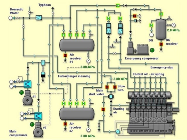
Q. WHAT ARE THE TYPES OF AIR COMPRESSOR ANDD IT'S WORKING PRINCIPLE?

ANS:- In an air compressor, air is compressed by pulling in atmospheric air, reducing its volume and increasing its pressure. 


There are two types of air compressor:-
  1. reciprocating type,
  2. rotary type
An air compressor is a versatile device used for supplying compressed at required pressure.
Eg. - for starting main engine of the ship, compressed air is required at 30 bar
-workshop purposes for removing dust
-spray paint

1. Reciprocating Air Compressor:-

  • A reciprocating air compressor makes use of piston(s) to compress air and store it in a storage tank(or reservoir) .
  • Based on the number of compression stages, reciprocating compressor can be a single-stage or double-stage configuration.
  • In the single-stage unit, only one piston is used to compress air, whereas there are two pistons for air compression in the double-stage air compressor.
  • Double - stage compressor are used to compress air at higher pressure. As in double stage the air which is compressed in primary stage is input for the secondary stage.
  • For marine purpose multistage compressor is used along with inter-coolers at every stage of compression and after-cooler (for maintaining the final temperature)
Since, it compresses air at much higher pressure so it is required to fit safety devices like:-
  1. Bursting discs are fitted on the cooler shells (At water side).
  2. Relief valves are fitted to discharge side for every stages.
  3. Moisture drain valve (unloader) are fitted at each cooler side
  4. Cooling water failure alarm.
  5. Low L. O pressure alarm.
  6. Delivery air high temperature alarm on after cooler outlet (Max 93°C)


2. Rotary Air Compressor

These are either vane or screw type.
  • Each stage pressure rise is limited to 7 bar only.
  • It requires a high speed drive.

(a) screw type

  • Over here, two spinning helical screws or rotors are involved for compressing air (instead of using pistons), hence the name.
  • As the screws mesh towards each other, air is compressed and pushed inside a storage tank.


(b)  vane type

  • A centrifugal air compressor is also called a dynamic compressor.
  • It is applicable when the demand for compressed air is high.
  • In this unit, a high-speed rotating impeller increases velocity of air, which is directed towards a diffuser that converts the velocity of air into pressure.
  • A centrifugal air compressor requires more energy to operate than the other two air compressors.


Air Compressor: Working Mechanism

  • In an air compressor, there are two major parts - a compressing system and a power source.
  • The compressing mechanism can be a piston, rotating impeller, or vane depending upon which type of compressor you are referring to.
  • As for the power, it is supplied by an electric motor or other energy sources.
  • The compressing mechanism, as the name suggests, helps in compressing atmospheric air by using energy from the power source.
  • The basic working principle of an air compressor is to compress atmospheric air, which is then used as per the requirements. In the process, atmospheric air is drawn in through an intake valve; more and more air is pulled inside a limited space mechanically by means of piston, impeller, or vane. Since the amount of pulled atmospheric air is increased in the receiver or storage tank, volume is reduced and pressure is raised automatically. In simpler terms, free or atmospheric air is compressed after reducing its volume and at the same time, increasing its pressure.

INTER-COOLER IN COMPRESSOR

Q. WHAT IS THE NECESSITY OF INTER-COOLER IN AIR COMPRESSOR?
ANS:
 To avoid excessive temperature rise associated with higher compression ratios, and to

1. Approach ISOTHERMAL COMPRESSION 

Result: Isothermal compression reduces compressor work hence saving in power.

2. Saving in power.

Reason As explained in point no. 1.

3. Volumetric efficiency is increased.

Reason: volumetric efficiency is the ratio of the amount of gas entering the compressor (suction) versus the amount of gas leaving the compressor (discharge).
since due to inter -cooling the volume of air is reduced due to reduction of temperature and hence the amount of air inlet after intercooler to next stage has increased which will also increase the amount of air discharge. Hence volumetric efficiency will increase.

4. Reduced the volume of air delivered and also reduced the compressor size.

Reason: When we compare a compressor having inter-cooler to the one having no inter-cooler , the compressor without intercooler will be bigger in size for the same output then the compressor with inter-cooler.

5. It reduces the air temperature.

Reason: Since it is a heat exchange process.

6. Due to less temperature suction & delivery valves remain cleaner without being fouled with carbonized oil.

Reason: High temperature operation requires frequent maintenance.

7. It allows good lubrication of the compressor piston.

Reason: As we know for proper lubrication(cylinder & piston ring) to establish there must be optimum temperature if temperature is high due to any reason, the lubrication will break which result in metal-to-metal contact and increases the wear.

8. Moisture separation is easier through inter cooler drains.

Reason: As we are using atmospheric air to compress it and by default atmospheric air contains moisture which is harmful in many ways so every intercooler is fitted with drain valve. Moisture will get condensed when it come in contact with cooling media and that will be drained by drain valve fitted in inter-cooler.

9. It also enables to deal with a greater weight of air for the same energy expended.

Reason: Due to reduction in volume the mass and the weight of air will increase for the next stage of compression.

Wednesday, 1 November 2017

oil fire in the bilge

       If there be an oil fire in the bilges, what type of fire extinguisher would you use and why?

   answer:
         
  1. First check the condition of fire; it is small oil fire in the bilge well.
  2. Then raise the fire alarm signal.
  3. Remove the combustible material near vicinity.
  4. It is a small fire, extinguish by foam portable extinguisher.
  5. Release the foam direct to the fire by deflecting it from another surface.
  6. Foam is lower specific gravity than oil or water that it will flows across the surface of oil and cover.
  7. The fire will stop by blanking with foam.

man-hole cover

    What precautions would you take before opening a man-hole cover of a fuel tank?
    answer:
    
  1. Gas free certificate
  2. Tank entry permit
  3. Risk assessment.
  4. Test tank atmosphere for toxic gases and oxygen.
  5. Breathing apparatus, resuscitation equipment to be kept ready at entrance.
  6. Life line to be put on.
  7. A spark proof hand torch light to be brought in
  8. Competent person to be kept on watch
  9. Smoking and naked light not allowed in vicinity.

Tuesday, 31 October 2017

CRUDE OIL WASHING(COW)

WHAT IS COW?

Crude oil washing (COW) is a system whereby oil tanks on a tanker are cleaned out between      voyages not with water, but with crude oil - the cargo itself

The solvent action of the crude oil makes the cleaning process far more effective than when water is used.

The system helps prevent pollution of the seas from operational measures.

MARPOL Annex I Regulation 13 (6) requires every new crude oil tanker of 20,000 tons dead weight and above to be fitted with a cargo tank cleaning system using crude oil washing.


WHY COW?

Previously, oil tanks on crude oil tanker were cleaned by water but this method of cleaning increased marine pollution and required bigger slop tanks to store left over residue and oil water mixture.

In order to prevent this problem, a better non pollutant way was introduced where in oil carg  of the tank itself was used to clean the cargo tanks.

When oil cargo is sprayed with pressure on tank walls and surfaces, the sediments sticking to the tank dissolves and converts into useful cargo which can be pumped out to the shore tanks.

This system virtually eliminates the requirement of slop tanks on ships and almost all cargo can be transferred to the shore.

Maintaining a pressure of at least 10 bar assists this process.

Before starting the operation
confirm all pre arrival checks are performed.
The complete COW operation to be discussed with ship and shore staff.
Signal and Emergency signs to be discussed to stop the operation between
     shore and ship staff.
Inert Gas plant to be working and oxygen content must be less than 5 %.

Fixed Oxygen analyser to be checked and calibrated for proper functioning.

Portable oxygen analyser should be made available and checked for proper
     functioning.

When the operation is under process
The inert gas values to be frequently checked- Tank pressure and O2 value.

A responsible person to be always present on deck.

All deck lines and valves must be frequently checked for any leakages.

Trim should be sufficient to assist the bottom washing of tanks.

The level of holding tanks to be continuously monitored to avoid overflow.

When the Operation is finished
Drain tank wash line off crude oil

Shut all the valves in the line used for the operation

Stop and drain all the machines involved in the operation

Drain all the cargo pumps after the operation is finished

Suspending Crude Oil Washing
Suspend COW operations immediately if:
The oxygen content of Inert Gas being supplied exceeds 8% by Volume.

Any indication of cargo oil leakage or malfunction in the COW system.

COW operation is not carried out in accordance with the COW operation plan, or if communication between the CCR and main deck is lost.

If the required necessary safety precautions as described and covered above cannot be followed.

If terminal instruct to do so 

Tuesday, 19 September 2017

AIR BOLLTE

AIR BOTTLE USED ON-BOARD SHIP

Image result for IMAGE OF AIR RECEIVER ON SHIP


  • IT IS A LARGE CONTAINER USED TO STORE COMPRESSED AIR.
  • IS IS ALSO KNOWN AS AIR RECEIVER AS IT ACTS AS AN AIR RESERVOIR.
  • PRESSURE OF COMPRESSED AIR IS AROUND 25-30 BAR.


PURPOSE
1. MAIN PURPOSE IS TO START MAIN ENGINE AND AUXILIARY ENGINE.
2. SUPPLIES CONTROL AIR TO MARINE ENGINES.
3. USED IN VARIOUS PNEUMATICALLY CONTROLLED DEVICES SUCH AS IF QUICK       CLOSING VALVE IS PNEUMATICALLY OPERATED.
4. HYDROPHORE SYSTEM TO SUPPLY WATER AT A CERTAIN PRESSURE USES                 COMPRESSED AIR.
5. SPRING AIR FOR EXHAUST VALVE IS SUPPLIED THROUGH AIR BOTTLE.
6. FOR CLEANING PURPOSES WHICH REQUIRES COMPRESSED AIR SUCH AS                 FILTERS.

SOLAS REQUIREMENTS
  • THE CAPACITY OF AIR BOTTLE SHOULD BE SUCH THAT IT IS CAPABLE ENOUGH TO PROVIDE 12 CONSECUTIVE STARTS FOR REVERSIBLE ENGINE AND 6 CONSECUTIVE STARTS FOR NON-REVERSIBLE ENGINES.
  • SOLAS PRESCRIBES THAT THERE MUST BE AT LEAST TWO IDENTICAL MAIN AIR BOTTLE AND ONE EMERGENCY BOTTLE ON EVERY VESSEL.
SAFETY DEVICES FITTED ON AIR BOTTLE
1. RELIEF VALVE
2. DRAIN VALVE
3. FUSIBLE PLUG
4. ALARMkps3005@gmail.com
5. PRESSURE GAUGE
SOME OTHER MOUNTINGS ARE
1. MAIN VALVE FOR STARTING AIR TO MAIN ENGINE
2. VALVE FOR AIR START TO AUXILIARY ENGINE
3. INLET VALVE FOR MAIN AIR COMPRESSOR
4. MANHOLE DOOR FOR INSPECTION PURPOSE (ELLIPTICAL SHAPE)

PURPOSE OF ALARM
  • AIR BOTTLE LOW PRESSURE ALARM IS FITTED ON THE RECEIVER.
  • ACTIVATION OF THIS VALVE IMPLIES THAT THERE IS NOT ENOUGH AIR IN THE BOTTLE.
  • SO MAIN ENGINE OR AUXILIARY ENGINE CAN NOT BE STARTED IN THIS CONDITION.

DURING EVERY WATCH
  • MUST DRAIN THE AIR BOTTLE.
  • KEEP DRAIN VALVE OPENED TILL ALL THE MOISTURE IS DRAINED.
  • IF MOISTURE CARRYOVER TAKES PLACE ALONG WITH COMPRESSED AIR , IT WILL CORRODE AIR BOTTLE.
  • IN ABSENCE OF DRAINING PROCEDURE OIL CARRYOVER WILL TAKE PLACE AND MAY RESULT IN FIRE.

MATERIAL
MADE UP OF CAST IRON.
INTERNAL SURFACE IS COATED WITH ANTI-CORROSIVE MATERIAL.


Image result for IMAGE OF AIR RECEIVER ON SHIP


Sunday, 17 September 2017

CENTRAL COOLING SYSTEM

  •     TO PREVENT PROBLEMS ASSOCIATED WITH SALT WATER SYSTEM  FRESH WATER IS USED FOR COOLING ALL THE COMPONENTS WHICH FORMS A CLOSED SYSTEM.
  • ·   SALT WATER PASSES THROUGH ONLY ONE SET OF PUMPS, VALVES, AND FILTER AND A SHORT LENGTH OF PIPING.
  • ·    THE SEA WATER TAKES WATER FROM THE SUCTIONS ON EITHER SIDE OF THE MACHINERY SPACE AND AFTER PASSING THROUGH THE COOLER IT IS DISCHARGED STRAIGHT OVERBOARD.
  •      THE FRESH WATER IN THE CLOSED SYSTEM IS TREATED WITH CHEMICALS TO PREVENT CORROSION OF THE PIPEWORK AND COOLERS. WITH CORRECT CHEMICAL TREATMENT, CORROSION IS ELIMINATED IN THE FRESH WATER SYSTEM, WITHOUT THE NEED FOR EXPENSIVE MATERIAL.


  •       IT CAN BE DIVIDED INTO THREE SECTIONS:-                                                              

                                     1. SEA WATER CIRCUIT                       
                                      2. HIGH TEMPERATURE CIRCUIT         
                                       3. LOW TEMPERATURE CIRCUIT
            COMBINATION OF THESE IS KNOWN AS CENTRALISED COOLING SYSTEM.
  • THE OUTLET OF JACKET COOLING WATER IS USED FOR THE EVAPORATION OF SEA WATER (FRESH WATER GENERATOR).
  • HIGH TEMPERATURE SYSTEM(HT) IS USED FOR
               - MAIN ENGINE LINER COOLING
                  -CYLINDER HEAD COOLING
                    -EXHAUST VALVE COOLING

  • ·        LOW TEMPERATURE(LT) USED FOR:-

§  FUEL VALVE COOLERS
§  AIR CONDITIONING CONDENSER
§  SHAFT BEARINGS
§  HYDRAULIC OIL COOLERS
§  MAIN AIR COMPRESSOR
. MAIN ENGINE AIR COOLER   
LUBE OIL COOLER

Image result for diagram of central cooling system onboard ship